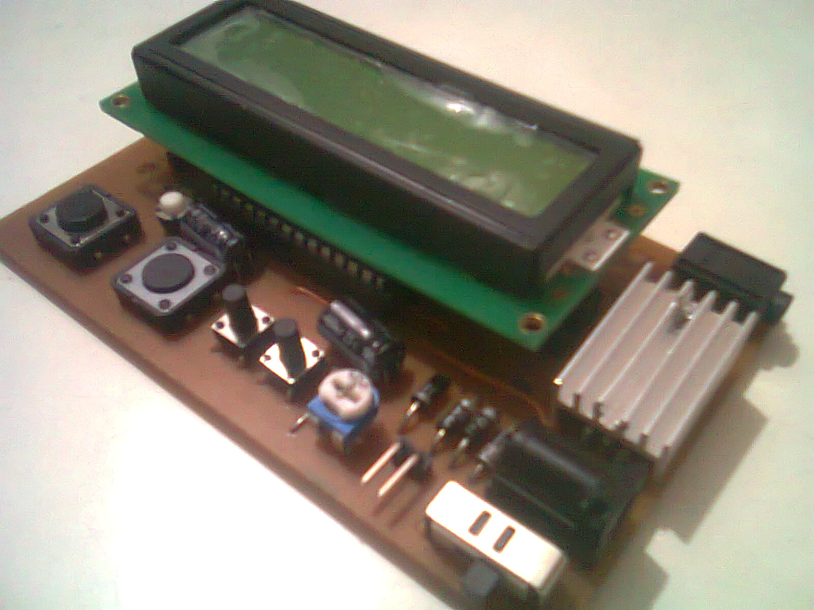
“Tachtastic”, a not so creative name for a tachometer. I was in my 2nd year of BE at the time and making a Tachometer seemed like a good idea and an easy project (according to a senior).
For those who don’t know, a tachometer is a device which can count the number of revolutions/rotations of something by use of some sensing mechanism. The sensing mechanism may or may not touch the device whose rotation is being measured. [Here is the Wikipedia Page for Tachometer]
I wanted to make a portable Tachometer which could run on a 9V battery and be small enough to fit in a pocket, yet be versatile to support multiple types of sensors and other basic functionality found in consumer tachometers.
Tachtastic – AVR Based Tachometer [Image Gallery]
Tachtastic Project Details
I choose AVR ATMega8 as it has enough pins(28 in total) to drive a Text LCD, a few buttons, etc. Sensor signal comes in from a 3.5mm Audio Jack which has 3 wires for (5V, GND and Signal), the signal goes into a comparator whose reference level can be set by an on-board trimpot, the signal then goes into the controller where it gets counted and displayed on the LCD. There are buttons to set how many signals the device sends in one revolution so as to calculate the actual revolution count, reset the count, etc.
As the sensor connects to the board via a 3.5mm jack, the sensor can be made separately as needed, I made 2 sensors, one for reflective sensing and another for light-break sensing of the revolution.
Coding
The coding etc was not very efficient also the counting is done manually in software without use of a timer so its max speed was quite less than expected but it worked much more accurately than I was hoping for. Using LCD library of Peter Fluery and updating the LCD once in every 2/3 seconds and the displayed values were averaged from the last 3 calculations.
PCB Design
I put too much time on the PCB Design of Tachtastic, testing many different layouts for the components and how it would be handled by one hand etc. I did some trials and when I had finalized the PCB Design, I first printed it on cardboard and tested the layout with actual components to check for any collisions etc. In the end the results were great, with a single sided small PCB and connectors for ISP, LCD Header and another header with some extra pins from the AVR for further expansion and any other add-on for the project.

Leave a Reply