

A few days ago, I posted a video+post about how to interface AVR with a text LCD (link: LCD Interfacing with AVR – [VIDEO + FILES]), but I had no time to explain some of the modifications which can be done in the library to get desired results.
In this post I will try to go line by line on the things which can be changed in the library. There are in totaal 3 files provided with the original library:
- lcd.h [Main file to include for the library]
- lcd.c [Contains all the routines for LCD interfacing]
- test_lcd.c [A test program to show what the library can do]
Our main concern will be with the lcd.h as it contains code which we can change to our needs, lcd.c contains all function definitions and nothing to change there unless you really know what you are doing and lastly the third file test_lcd.c is a test program written by the original author of the library Peter Fleury to show what the library can do and demos the functions which can be used with the library, a good idea will be go through the file to see working code example.
lcd.h:
The comments in the file are enough to explain everything that needs explanation (but some of my friends are just persistent to not try to understand what is written there, so here goes).
- Line 47: #define XTAL 4000000
This value may be changed to the project’s clock which is being used or this can be ignored if the clock is mentioned in the main file or in the compile options. - Line 54: #define LCD_CONTROLLER_KS0073 0
Use 0 for HD44780 controller or 1 for KS0073 controller, this refers to the controller which is inside your LCD, so check the datasheet of your LCD to be sure, the first one HD44780 is the most common. - Line 60: #define LCD_LINES 2
Number of lines the LCD display can show. - Line 61: #define LCD_DISP_LENGTH 16
Maximum characters which may be displayed per line on the LCD. - Lines 62 to 66: Some more defines, usually dont need to be changed but if the display seems to start from middle of the screen or the text skips some spaces on each line try checking these values in the datasheet of your LCD and change as needed.
- Line 67: #define LCD_WRAP_LINES 0
0 to wrap text to multiple lines and 1 for no wrapping
1 to wrap text to multiple lines and 0 for no wrapping (corrected thanks to Maaz) - Line 70: #define LCD_IO_MODE 1
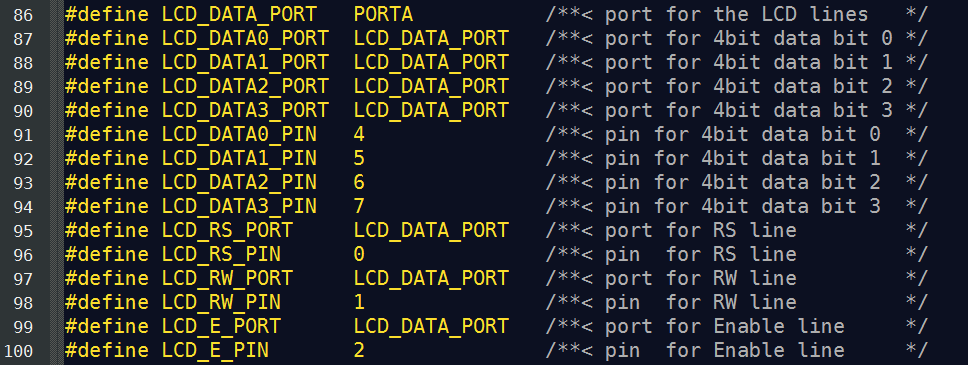
How the LCD is interfaced, 1 is for normal I/O mode and 0 if the data is coming from some external memory (you won’t need to put zero if you are reading this post). - Lines 86 to 100: This is the most important portion of the library, here you can select how the LCD is connected to the AVR, although this is straight forward; i.e. to put LCD on Pins 0-6 of port A just write
#define LCD_PORT         PORTA        /**< port for the LCD lines   */
#define LCD_DATA0_PORT   LCD_PORT     /**< port for 4bit data bit 0 */
#define LCD_DATA1_PORT   LCD_PORT     /**< port for 4bit data bit 1 */
#define LCD_DATA2_PORT   LCD_PORT     /**< port for 4bit data bit 2 */
#define LCD_DATA3_PORT   LCD_PORT     /**< port for 4bit data bit 3 */
#define LCD_DATA0_PIN    0            /**< pin for 4bit data bit 0  */
#define LCD_DATA1_PIN    1            /**< pin for 4bit data bit 1  */
#define LCD_DATA2_PIN    2            /**< pin for 4bit data bit 2  */
#define LCD_DATA3_PIN    3            /**< pin for 4bit data bit 3  */
#define LCD_RS_PORT      LCD_PORT     /**< port for RS line         */
#define LCD_RS_PIN       4            /**< pin  for RS line         */
#define LCD_RW_PORT      LCD_PORT     /**< port for RW line         */
#define LCD_RW_PIN       5            /**< pin  for RW line         */
#define LCD_E_PORT       LCD_PORT     /**< port for Enable line     */
#define LCD_E_PIN        6            /**< pin  for Enable line     */
Now, the tricky (actually not so tricky) part comes when you wish to connect the LCD in such a way that the data lines are on some other port and the control lines are somewhere else.
Like here, I wanted to use ADC so Port A was not completely free and I had already filled Ports B and D I had 3 I/O lines on Port A left and I was using JTAG so 4 I/O lines were left on Port C as well (talking about ATMega32), so I changed the LCD pin defines as follows:
#define LCD_DATA_PORT   PORTC           /**< port for the LCD lines   */
#define LCD_CTRL_PORT   PORTA           /**< port for the LCD lines   */
#define LCD_DATA0_PORT  LCD_DATA_PORT   /**< port for 4bit data bit 0 */
#define LCD_DATA1_PORT  LCD_DATA_PORT   /**< port for 4bit data bit 1 */
#define LCD_DATA2_PORT  LCD_DATA_PORT   /**< port for 4bit data bit 2 */
#define LCD_DATA3_PORT  LCD_DATA_PORT   /**< port for 4bit data bit 3 */
#define LCD_DATA0_PIN   0               /**< pin for 4bit data bit 0  */
#define LCD_DATA1_PIN   1               /**< pin for 4bit data bit 1  */
#define LCD_DATA2_PIN   6               /**< pin for 4bit data bit 2  */
#define LCD_DATA3_PIN   7               /**< pin for 4bit data bit 3  */
#define LCD_RS_PORT     LCD_CTRL_PORT   /**< port for RS line         */
#define LCD_RS_PIN      5               /**< pin  for RS line         */
#define LCD_RW_PORT     LCD_CTRL_PORT   /**< port for RW line         */
#define LCD_RW_PIN      6               /**< pin  for RW line         */
#define LCD_E_PORT      LCD_CTRL_PORT   /**< port for Enable line     */
#define LCD_E_PIN       7               /**< pin  for Enable line     */
So as you can see, best of both worlds; JTAG + LCD. The numbering of the pins in the defines can also be changed if needed (to simplify PCB connections etc).
If you read on ahead in the lcd.h file, you will see some more defines, relating to the commands of the LCD controller IC HD44750 (again see datasheet) and more further below you will find definitions of all the functions that this library provides.
I am attaching all relevant files with this post so you may easily download them and use.
Software Used:
- AVR Studio with WINAVR (AVR GCC)
- Proteus for Simulation
- LCD Interface Library from Peter Fleury (http://www.jump.to/fleury)
[download id=”1″ format=”2″]
2 responses to “LCD Interfacing with AVR – [Library Explanation]”
[…] UPDATE: Here is the Explanation post link: LCD Interfacing with AVR – [Library Explanation] […]
[…] status to the UART as a console). Peter Fleury has a AVR UART Library as well along with his AVR LCD Library which I explained here some time […]