

Today I was searching about how to breadboard on MultiSim, found many tutorials on the topic, but in one, I found this amazing little concept, explained, once and for all……
The copy of the text is;
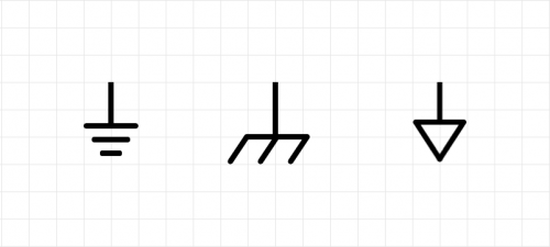
The Concept of a Ground
Nevertheless, this simple circuit does introduce a very powerful concept. Notice that we did not place a ground on the breadboard and no error occurred. Hopefully, this rather subtle point help clarifies the concept of a ground: it is just a symbol on your circuit that indicates your reference node. A circuit does not need to have an explicit ground connection to Earth (unless you are dealing with very high voltages and want to provide a safe return path). Many circuits do not have any explicit ground connection to Earth.
The circuit being referred to is a very simple circuit, I copied this after the writer explained how to convert a MultiSim Schematic into a breadboard using MultiSim, but then he realized that there is no ground connection required when designing on a breadboard.
The complete article is here…..
5 responses to “The Ground Problem”
[…] CONCEPT of GROUND, okay, I didn’t wrote it, just copied it… but do take a look… […]
Then why were you connecting to the GROUND the other day…..
thanks for this post but I already know this…
It is not so the current always flow towards low potential area and ground is relatively low as compared to a positive current because it provides us 0volts which is exactly be a less thing for a thinking guy and for this reason I ground that
[…] (Pin 11) For the ground connection, that’s enough […]