What you see above is a project made for my Power Electronics Course, last term, finally completed and submitted. It is an AVR based board having 2 optically-isolated TRIACs for AC Power Control and implements both Phase Control and Burst Fire Control on each of the TRIACs. Controllable by an NEC IR Remote, shows status on Text LCD and the complete code was written in Arduino IDE [though there is some non-arduino/AVR code too].
The circuit above can be distributed into 3 parts, Power Supply, Controller and TRIACs.
Power Supply
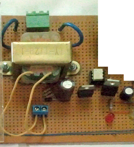
The Power Supply for this board comes in the form of 220V AC from the wall outlet into the green terminal at the top-centre, which gets stepped-down by the transformer to 20V AC. The 20V AC is half-rectified by the 1N4007 diode [above the blue terminal] and is fed into the 15v regulator 7815 which feeds the next regulator 7805 to get a stable 5V DC supply for the controller circuitry.
The small white IC that you see is H11AA1 which detects the zero-crossings in the AC Line, I fed it stepped down AC supply [after the transformer]. It gives a pulse at every zero crossing and the whole AC Control relies on the signals coming from this IC. the Zero detect pulse goes to the INT0 pin of AVR, D2 pin on Arduino.
And what project would be complete without a Red LED to indicate Power.

Controller – AtMega8 / Arduino
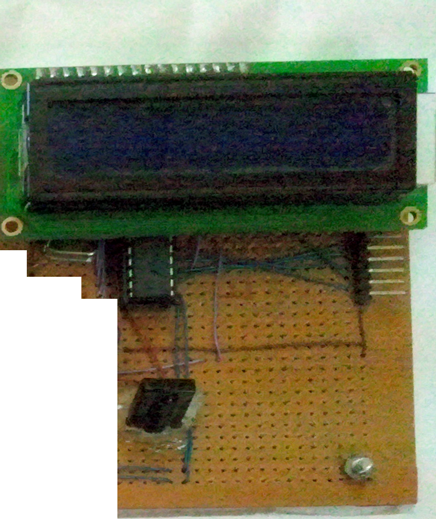
I used an AtMega8 as the controller in this project running at 16MHz (hidden beneath the LCD) and programmed it via the Arduino IDE, using a USBasp programmer, the connector to the right is the ISP connector.
I used the Arduino environment as I wanted to use the IR Remote Library from AdaFruit and the LCD Library along with wanting to keep it simple and clean. The pinout of the LCD and the IR sensor (Black Component at the bottom) etc is provided in the arduino code, so I will not dwell in the schematic details here. It is to note that the IR remote I had was not working properly with the library so I had to do a few hacks in the original library. [code details in a later post]

[download id=”11″ format=”2″]
AC Power Control – TRIACs
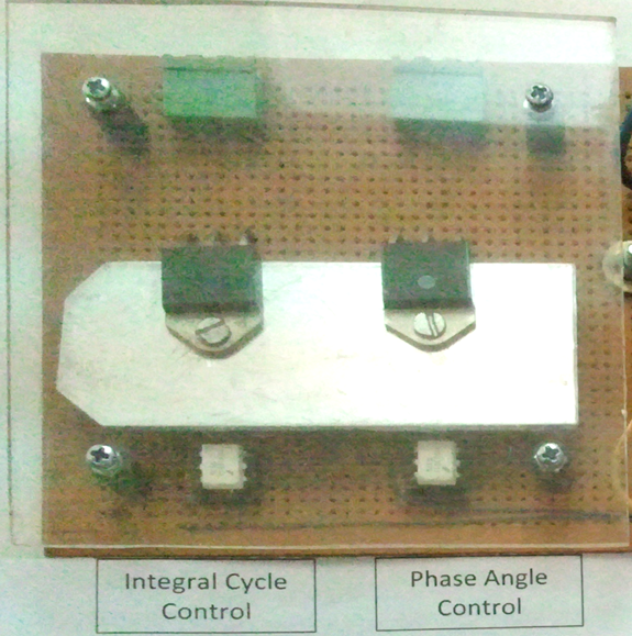
This is the portion of the circuit which controls AC Power, the TRIACs used are BTA41 which are coupled to the controller by optical isolators MOC3011 (the white ICs). I am a bit paranoid when working with high voltage so I put up a plastic sheet over the 2 TRIACs and the bottom side is hidden with a card-sheet so no joints are exposed from below as well. Both TRIACs share teh same heat sink, an aluminum piece I found lying around, drilled it to use with the TRIACs. As labelled, one TRIAC controls the power by INtegral Cycle control method and the other uses Phase Control.

Code and other details on how the circuit is working will come in another post.

