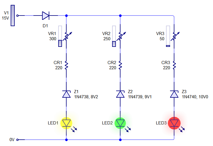
We were required to make sort of a final project for the first year of our studies as the year came to an end, the project was for the subject of PCB Manufacturing, so more emphasis on design of PCB than on the electronics was needed. While some of my friends did made exceptional (and complex) projects (I might posts pics and videos later), I picked a much simpler task; a Voltage Indicator Circuit, using only Discrete Components.
A Voltage Indicator is a simple circuit which indicates voltage either by showing the actual voltage value or providing visual indication of the applied voltage, the first step was to lookup on Google but most of the circuits available used ICs (Op-Amps) and they themselves required a battery to be operated.


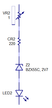
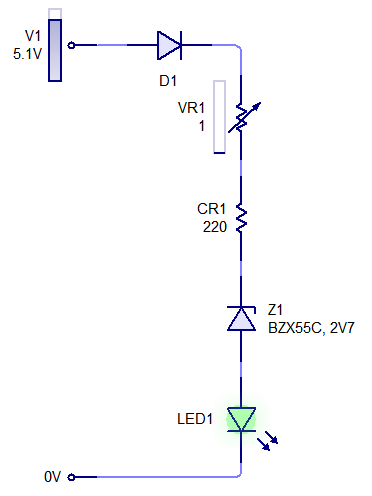
So, after discussing with some friends and thinking of a more simpler solution, I (+ a friend) came up with a very Simple Voltage Indicator circuit, using ONLY Dirscrete Components, it doesn’t need a battery to be operated and can be made to show either a single voltage or a voltage range, the actual circuit is a simple block consisting of a Resistor, a Zener Diode and an LED. The more blocks you attach together the more range you will get.
Possible Application: I thought it would be best used as a simple battery voltage indicator on battery operated circuits, as this can be easily hooked up to the battery of a circuit with a SPDT switch; flipping the switch will indicate the battery volatge.


How it Works
Since this circuit consists of simple building blocks, lets just take one and see what happens…. At the top, there is a variable resistor of 1k ohm, followed by a fixed resistor of 220 ohm connected in series, both function as current limiters, though the pot may be used to adjust the brightness of the LED or to calibrate the voltage to be tested. After that is the Zener Diode, this is the heart of the circuit, the zener voltage is the one which sets the actual voltage to be tested. Then there is an LED, how else can we get any kind of indication. You connect positive voltage at the top and GND at the bottom to check the voltage.
My Circuit PCB
Here are pics of the PCB which I made as my final project, I added some capacitors and additional diodes, just to increase the component density on the board and to add a sort of delay effect to the LEDs.
[nggallery id=1]

